PROJECT BACKGROUND
The Darkness Serenade by Colin Higgs
medium: interactive installation
space requirements: 2.5 square metres
There is something very engaging about the unexpected. The unexpected in this generative art installation is in the direct and gestural movement the spectator can have on a graphical interactive display and how they react to or notice the sounds they are making. There is a lot for the person to learn about the work. How they fit into it. What they add to the work. How they can construct both unique and unusual sounds and graphics that they feel are part of a performance. Their performance. They are the conductors of the piece.
The project is an installation of a symbolic journey in darkness with an element of hope. The spectator embarks on a symbolic journey of interaction and creation of both sound and visuals.The performance starts up by the spectator entering a small light-projected arena. They stay in a centre area for until the sensors pick them up and all the system is reset.
The graphics which are projected onto the floor are reset and so is the sound score to nothing. The person notices that as they travel around the projected arena the graphics seems to be approaching them or backing off them depending on the type of motion they make. They also notice that the sounds they create are made by there own movements. Each time they move they create a series of sounds. The darkness side of the piece of work corresponds to a black generative graphic that spreads towards the spectator if she/he does not move.
The hope of the piece lies in the somewhat dissonant landscape sounds created by the movement of the person. Partly noise and partly tonal.
The balance between the graphic and sound (darkness and hope) lies between the number of movements and distance moved relating to the numbers of sound samples generated and the way the graphic moves towards the spectator or away from the spectator. The sound will also be influenced as well by the persons movement (motion detection algorithm).
Creative Motivation
The motivation for the piece was driven by a soundscape I made in MAXMSP, using a Fourier transform (this was the sound used in maxmsp called “S00_FOURIER”). I found the sound quite haunting and began to think about how visuals and interaction can form the basis of a artwork.
Future Development
For further development I would like to work with a contemporary dancer in using the artwork as part of a performance. I would like to see it as a first step with the work, I would intend to develop a group performance (2 or 3 people).
Why make the work? When I see a person interact with my artwork sometimes I feel it elevates my work: it takes it into a new unexpected direction. This for me is quite beautiful and unexpected and very rewarding so thats why I wanted to make it. In terms of who is it for? I would say the basic version would be for everyone. People find it stimulating and unexpected (especially the gesture interaction). In terms of a performance (dance) piece I would use it only as the start of something and develop it further in terms of a narrative piece of audio visual work.
THE RESULT
DARKESSSERENADE POPUP
This project has an overlap with my Machine Learning project. Half of this project was designed for a MAXMSP sound interactive experience and the graphic experience was designed for machine learning. The max project was further separated by removing all the machine learning code and only using hardcoded inputs and outputs. A summary of the differences between the 2 projects are as follows
PROJECT INPUTS OUTPUTS
MAXMSP: kinect —-> OSC—> processing graphics /MAXMSP
MACHINE: kinnect -> OSC–>WEK HELP/WEK OSC–> processing LEARNING graphics /
. /MAXMSP
The machine learning installation is using 20 trained inputs.
The MAXMSP installation is using 9 hardcoded inputs.
See figure below:

Hardcoded inputs made in the processing sketch for the kinect capture:
// oscFloatx1 – average position of person in x uses depth data
// oscFloaty1 – average position of person in y uses depth data
//
// oscFloatvel1 – average velocity of person detected
// oscFloataccel1 – average acceleration of person detected
// countMinutes – count in minutes since simulation started
// oscFloatSignal – Has kinect detected a person? yes 1 no 0
// oscCorners – Has kinect detected any gestures? (0-no 1-2-3-4==n-s-w-e)
// oscStretchx1 – if any gestures have been detected send x cord
// oscStretchy1 – if any gestures have been detected send y cord
MAXMSP CODED INPUTS FOR SOUND:
The controller of all the sounds is called: S_CONDUCTOR1
It controls both the sound duration and events and each mapping in MAXMSP. Remap the persons Y position to play a selected event 1-7. The mapping was zmap 0 480 1 7. Remap a persons x-position to a time. zmap 0 680 20000 35000.
Remaps the persons X position to 20-35 seconds for the duration of a sample.
The selections:
S00_FOURIER: always triggered on a users erratic movement. Acceleration > 3. This generative sound is always present in the soundscape.
The other sounds are non-permanent sounds and are generative and also make use of samples. They are all triggered by the S_CONDUCTOR1 patch:
sel 1- Play music S01_STARTA
sel 2- Play music S02B_ACCEL & S03_SAMLPLES
sel 3- Play music S03_SAMLPLES & S04_ACCEL
sel 4- Play music S04_ACCEL & S05_ACCEL
sel 5- Play music S05_ACCEL & S06_SAMPLES_RESTART
sel 6- Play music S06_SAMPLES_RESTART & S02B_ACCEL
sel 7- Play music S01_STARTA & S02B_ACCEL
The detail of the sound creation will be looked at below. Here we look at the choices and what they mean.
S00_FOURIER – Is a generative sound always playing in the background and is triggered by the persons acceleration. Its distinctive in different tones and can be crescendoed by the acceleration (a series of different tones can be triggered).
S01_STARTA- Is a poly 16 voice noise patch. Its creates noise with different central noise frequencies placed into a reson filter. Its a subtractive filter using pink noise and gives us a frequency centred noise output similar to the fourier noise transform output in patch 00. Its pitch is further modulated by a continuing random number.
S02B_ACCEL & S03_SAMLPLES – 02b is a generative sound ( a “comb” filter) and changes settings every 3 seconds and is triggered when the acceleration is greater than 5. 03 samples is triggered only by its initial call via the conductor, however, as to which sample is played is dependent on the persons Y position. The construction of the two sounds means either one is heard : acceleration causes 02b to be triggered and NO Movement causes the samples to be called. They play off each other,
S03_SAMLPLES & S04_ACCEL- 04 is a generative sound ( a “fffb~” filter) a subtractive filter. Its mapped using a persons X position and using this to map a frequency to make harmonic packets from pink noise. Again the use of samples and generative sounds (03 samples) makes for a great combination as they too play off each each other. The samples are only heard if the generative sound is not.
S04_ACCEL & S05_ACCEL- Plays two generative sounds. 04 is a generative sound ( a “fffb~” filter) a subtractive filter. 05 is also a generative sound based from the FM_Surfer patch by John Bischoff. It makes a FM synthesiser sound. 04 generative sound is mapped to the position of the person and 05 generative sound is mapped to the acceleration is greater than 8 trigger.
S05_ACCEL & S06_SAMPLES_RESTART 05 is also a generative sound and is combined with a samples patch. Again both play off each other. 06 samples and 03 samples are completely different.
S06_SAMPLES_RESTART & S02B_ACCEL – Samples are played against a generative patch. Off against 02b is a generative sound ( a “comb” filter) .
S01_STARTA & S02B_ACCEL- Two generative patches play together. 01 patch changes sound changing on the x-position of the person. 2b is a generative sound ( a “comb” filter) and is triggered by the persons acceleration
PROCESSING GRAPHICS CODED INPUTS FOR DISPLAY:
Based on the 9 inputs from the Kinect capture code:
PERSON POSITION X AND Y – obtained using the persons depth positioning using the average values of all the paid depths obtained.
VELOCITY VALUES ABS – Calculates the average velocity using last reading of velocity
ACCELERATION VALUES – Calculates the average acceleration using last reading of acceleration
TIME PASSED IN MINUTES – Since the sketch started
SYSTEM ACTIVE OR PASSIVE – Do we capture a reading?
GESTURES SPLIT INTO 4 SIGNALS – We calculate the gestures based on the extreme values of leftmost, rightmost, topmost and botmost signals detected.
GESTURES X AND Y – The positions of the extreme gestures are calculated
These parameters are then sent on to both the graphics sketch (in processing) and the sound collective sketch (MAXMSP) using the OSC library for processing.
Re-mapped values in the graphics sketch:
Once the OSC values are received in the graphics sketch they are further changed as follows:
oscFloatx1 = map(theOscMessage.get(0).floatValue(), 0, 640, 0, 1920);
oscFloaty1 = map(theOscMessage.get(1).floatValue(), 0, 480, 0, 1080);
oscFloatvel1 =map(theOscMessage.get(2).floatValue(), 0, 100, 0, 100);
oscFloataccel1 = map(theOscMessage.get(3).floatValue(), 0, 200, 0, 200);
oscCountTime = int(map(theOscMessage.get(4).floatValue(), 0, 20, 0, 21));
oscFloatSignal = int(map(theOscMessage.get(5).floatValue(), 0, 1, 0, 1));
oscCorners = int(map(theOscMessage.get(6).floatValue(), 0, 4, 0, 4));
oscCornersx1 = map(theOscMessage.get(7).floatValue(), 0, 640, 0, 1920);
oscCornersy1 = map(theOscMessage.get(8).floatValue(), 0, 480, 0, 1080);
// Remappings based on the above readings from the Kinect
oscAccelMax = max(oscFloatvel1, oscFloataccel1);
oscAccelStdDev = max(oscFloatvel1, oscFloataccel1);
oscposXStdDev = max(oscFloatvel1, oscFloataccel1);
oscposYStdDev = max(oscFloatvel1, oscFloataccel1);
// These were embedded and coded directly into MAX MSP
oscConductEvents = int(map(oscFloaty1, 0, 1920, 1, 10));
oscConductTime = map(oscFloaty1, 0, 1080, 10000, 30000);
// Remappings
oscGraphicsTrigger=map(oscAccelMax, 0, 200, 5, 12);
oscColourTrigger=map(oscAccelMax, 0, 200, 8, 12);
oscParticlemaxspeed = map(oscFloatx1, 0, 1920, 0.8, 18);
oscParticlemaxforce = map(oscFloaty1, 0, 1080, 1, 10);
oscMixGraphics = (int(theOscMessage.get(4).floatValue() ) % 5) +1;
Adding Variety
13 and 14. Graphics Trigger Values/Color Trigger Values.
These values controlled if a graphic is created and if it changes colour. They trigger different graphic counters and add all of the “bright swarms” and “black swarms”.
If the acceleration of the person was above either Graphics Trigger Values/Color Trigger Values they would trigger new graphics and change those graphics respectively.
oscAccelMax = max(oscFloatvel1, oscFloataccel1);
oscGraphicsTrigger=map(oscAccelMax, 0, 200, 5, 12);
oscColourTrigger=map(oscAccelMax, 0, 200, 8, 12);
As shown above the graphics trigger is using “oscAccelMax” ( the max of acceleration and velocity which ever is largest at the time). New graphics are generated when acceleration is greater than 5-12 and colours of the graphics are changed when the acceleration is 8-12
These were logical choices to choose for the activation of new shapes to be produced on the floor when the graphics trigger control value was exceeded by a fast/erratic movement.
The Graphics Trigger Values limits were further constrained to produce reasonable results. (So a sudden movement would push the acceleration max up dramatically but this movement was further confined to medium changes. Otherwise hardly any graphics would be made.) The Color Trigger Valuess limits were restricted as well to give a good balance between non-excited graphics colours and excited graphics colours
15. and 16. Particle max speed and Particle max force.
oscParticlemaxspeed = map(oscFloatx1, 0, 1920, 0.8, 18);
oscParticlemaxforce = map(oscFloaty1, 0, 1080, 1, 10);
These parameters control all the particle swarms particle speed and force of attraction to the target. These outputs were mapped on x and y of a person.
17. Mix up Graphics 1-5.
oscMixGraphics = (int(theOscMessage.get(4).floatValue() ) % 5) +1;
An arbitrary solution based on the acceleration value of the person and selects 1 of 5 values. This value controls when different graphics are seen when the correct counter values for each graphics have been triggered.
18,19 and 20. Gestures.
oscCorners = int(map(theOscMessage.get(6).floatValue(), 0, 4, 0, 4));
oscCornersx1 = map(theOscMessage.get(7).floatValue(), 0, 640, 0, 1920);
oscCornersy1 = map(theOscMessage.get(8).floatValue(), 0, 480, 0, 1080);
The gestures calculate extreme Kinect depth values either top or bottom or left or right. They will directly control the position of all of the graphic positions if they are detected.
The gestures were probably the best visual cue feature in the work. Everyone loved them. They were triggered by the distance between extreme depth value pixel readings from the average depth pixels picked up. They were immediate and developing them further on the graphics side would be nice feature that they change the size of the graphics when they were activated. For the sound would be nice if they changed the generative sounds that were chosen currently they trigger generative sounds.
Instructions for compiling and running your project.
The setup is as follows.

What software tools were used?
The data inputs: kinnect input via processing and OSC
Data outputs: all outputs sent to both MAXMSP AND PROCESSING
The inputs that detect if someone is there or not are being detected by using a Kinect using infrared dots. A Kinect is needed to run the project properly via processing. However, the mouse inputs can be used for testing purposes and a processing sketch with the mouse setup for making up outputs has also been made. The Kinect passes on positional, velocity,acceleration data and gesture data as well.
The input Kinect processing sketches used:
sketch_15_KINECT_INPUT_SENDSOSC
sketch_15mouse_MAXMSP_INPUT_SENDSOSC
Next the outputs from the Kinect or the mouse feed into the sound assembly with MAXMSP with the main patch SALL.maxpat and the graphics which were made in processing with the patch sketch_TEST33A_9inputs_MAXMSP_INPUTOSC.
The Graphics
The Graphics were based upon a Shiffman swarm algorithm https://processing.org/examples/flocking.html then modified to have different behaviours depending on the last distance the particle has travelled to and the distance from current particle position to the target position. The Particles had the ability to apply different kinematics solutions depending on the answers to these two questions. Further to one swarming solution multiple swarms were coded with different kinematics on top of this to look completely different from the original particle swarms.
The processing sketch consists of 5 particle swarms called:
Ameoba02Vehicle: cell like but big
AmeobaVehicle: cell like but small
BrightVehicle: tadpole like
DarkVehicle: small black particles
EraticVehicle: like a “firework” pattern that uses a lissajous pattern
These are triggered by the Graphics Trigger Values. This in turn triggered counters for all the the graphics which keep getting updated. However, when they are seen is triggered by “Mixup Graphics” value that keeps changes it mind about the trigger values.
If the person does not move or the distance to the target is within a certain range that has been set up for each swarm they will be deleted. If the distance to the target is within another certain range all the particles have a random target algorithm incorporated.
The patch which contained all the graphics of the swarms:
sketch_TEST33A_9inputs_MAXMSP_INPUTOSC
The MAXMSP Sound Control:
All the sketches are contained within the “SALL” patch.
Which consists of 8 patches:
S_CONDUCTOR1 – decides which sounds to play for and how long for (from S01 to S06). Gets readings from Kinect based on a persons position in X and Y. All of the generative and samples only play for “x'” seconds if called by S_CONDUCTOR1.
The following sounds and samples can be called:
S01_STARTA – A 16 voice poly patch that uses noise with a Reson filter to
output random noise values
S00_FOURIER – Uses Noise in fourier transform to output discreet packets of
noise that slowly dissipate
S02B_ACCEL – Another filter comb~ uses a sample input to mix to timings of
the samples.
S03_SAMLPLES- Uses 9 samples in the patch and mixes them together with
different timings
S04_ACCEL – Uses a fffb~ filter a subtractive filter uses pink noise to give
discreet packets of noise similar to S01_STARTA patch.
S05_ACCEL – Based on the fm-surfer patch. A frequency modular syntheziser
S06_SAMPLES_RESTART – Uses 9 another set of samples in the patch and mixes
them together with different timings.
03_SAMLPLES_REV & 06_SAMLPLES_REV- Same as the other sample patches but only uploads one sample at a time. Was not used.
Max code related origins:
The code for sound was based upon :
S00_FOURIER : This code was partially based on The forbidden planet patch.
S01_STARTA patch: This code was partially based on Polyphony Tutorial 1: Using the poly~ Object
S02_ACCEL patch: This code was based on MSP Delay Tutorial 6: Comb Filter
S04_ACCEL patch: This code was based on Filter Tutorial 4: Subtractive Synthesis
S05_ACCEL patch : This code was partially based on FM-SURFER patch.
S03_SAMLPLES & S06_SAMPLES_RESTART: This code was partially based on the Sampling Tutorial 4: Variable-length Wavetable
S06_SAMPLES_RESTART & S03_SAMLPLES: This code was partially based on the Sampling Tutorial 4: Variable-length Wavetable
03_SAMLPLES_REV & 06_SAMLPLES_REV: This code was partially based on the Sampling Tutorial 4: Variable-length Wavetable
S_CONDUCTOR1 patch: My code.
FILTER INFORMATION (mainly for my own comprehension)
The Fourier Transform Patch
This graphic EQ implementation is based on a frequency-domain signal processing technique. The input signal is converted to a frequency-domain signal using the Fast Fourier Transform (FFT). It is then convolved (complex multiply) with another frequency-domain signal, based on a function describing the desired spectral attenuation. The resulting signal is then converted back to a time-domain signal using the inverse FFT (IFFT). The number of “bands” in this implementation is given by the FFT’s window size. In this case, it is 1024 samples long, yielding 1024 / 2 = 512 bands, evenly covering the frequency range (sampling rate / 2). Each band’s width in Hz is (1/2 * sampling rate) / 512. Probably around 43 Hz in your case.
Comb filter
An example of such an object is comb~, which implements a formula for comb filtering. Generally speaking, an audio filter is a frequency-dependent amplifier; it boosts the amplitude of some frequency components of a signal while reducing other frequencies. A comb filter accentuates and attenuates the input signal at regularly spaced frequency intervals — that is, at integer multiples of some fundamental frequency.
Technical detail: The fundamental frequency of a comb filter is the inverse of the delay time. For example, if the delay time is 2 milliseconds (1/500 of a second), the accentuation occurs at intervals of 500 Hz (500, 1000, 1500, etc.), and the attenuation occurs between those frequencies. The extremity of the filtering effect depends on the factor (between 0 and 1) by which the feedback is scaled. As the scaling factor approaches 1, the accentuation and attenuation become more extreme. This causes the sonic effect of resonance (a ‘ringing’ sound) at the harmonics of the fundamental frequency.
The comb~ object sends out a signal that is a combination of a) the input signal, b) the input signal it received a certain time ago, and c) the output signal it sent that same amount of time ago (which would have included prior delays). In the inlets of comb~ we can specify the desired amount of each of these three (a, b, and c), as well as the delay time (we’ll call it d).
Technical detail: At any given moment in time (we’ll call that moment t), comb~ uses the value of the input signal (xt), to calculate the output yt in the following manner:
yt = axt + bx(t-d) + cy(t-d)
The bx(t-d) term in the equation is called the feedforward and the cy(t-d) term is the feedback.
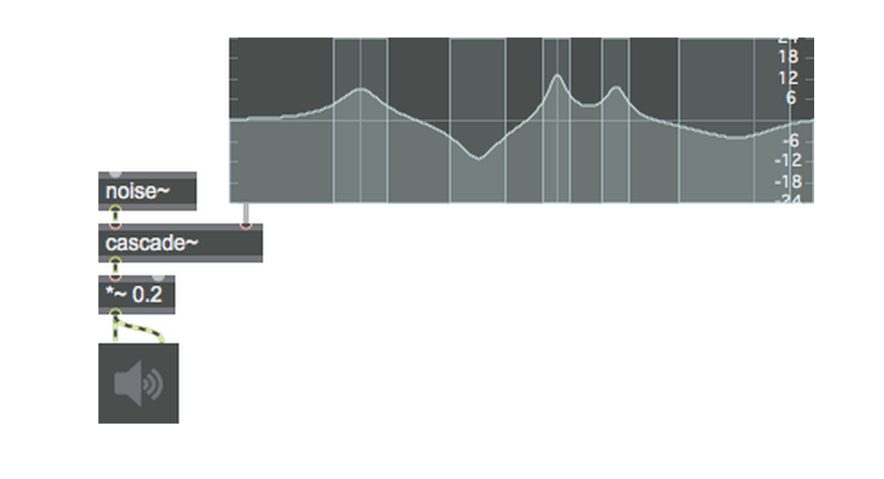
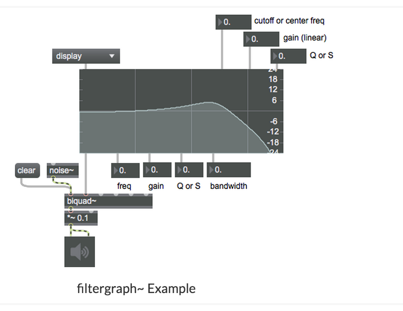
The subtractive THE FFB FILTER
The fffb~ object stands for Fast, Fixed, Filter Bank. Unlike the cascade~ object, which implements a number of biquad~ filters in series, the fffb~ object arranges a number of reson~ objects in parallel, which is to say that the settings of one filter will not affect any of the others. The fffb~ object takes a number of arguments which set its behavior: the number of filters, the base frequency of the filter bank, the ratio between filters, and the Q of the filters. All of the parameters of the object with the exception of the number of filters can be changed with Max messages; the number is fixed because, as we can see, each filter connects to a separate outlet. This allows us to create filter banks, where we can ‘tap’ each bandpass filter individually:
FM Surfer
“The first step is to admit that no one really understands FM synthesis. There, doesn’t that make you feel better? By putting your trust in a higher power(in this case, the “random” object), you can spare yourself and your loved ones a lot of rebooting.”
This patch simulates a TX81Z-style FM synthesizer, but the parameters are randomly generated. John Cage meets John Chowning.
Poly~
The poly~ object takes as its argument the name of a patcher file, followed by a number that specifies the number of copies (or instances) of the patch to be created. You’ll want to specify the same number of copies as you would have had to duplicate manually when implementing polyphony the old-fashioned way. Here’s an example of the poly~ object.
Working with samples I came up with 2 solutions in working with 10 possible samples to call. The two solutions are shown in these patches:
Both of them use:
wave~ reads from a portion of a buffer~ to produce a repeating waveform, given a signal input that goes between 0 and 1 (for example, using a phasor~) to define the position in the buffer. Every sample has been chosen to start from a selected in pointing its speed has been chosen.
Both patches have 9 different samples but how they go from one sample to another is different.
S06_SAMPLES_RESTART – Uploads all nine samples at the start but only plays one sample at a time. Sends messages of the volume to all nine samples which are changing depending on the selected sample to be played. Its a giant mixing desk.
06_SAMLPLES_REV– chooses to import the samples chosen on the fly. Only one sample is ever loaded to be played but still uses the volume messages to control all nine samples volume.
Summary in running the installation:

A reflection how successful your project was in meeting your creative aims.
For a hard-coded solution the results were only a 80% of what I achieved with Machine Learning. The results were very good. It was impossible to say which was the Machine Learning and which was hard coded. Both outcomes were very good.
The hardcoded Gestures were one of the best features of the work; it made the whole piece so much a part of the user interacting with the piece. They felt so much more connected to the pieced it left personal for them. The code was quite logical and it was possible for further code to predict which was the left and right hand leading to even more gesture outcomes.
The sound even though controlled mainly by using the position of X and Y of the person also worked surprisingly well in using a “Conductor” to predict which sounds should be played and when. The calling of the patches through the conductor (although a very straight forward solution) also gave me an open solution. It could be endlessly expanded. As the sounds called could be endless and generative (not fixed as well). I was very pleased with this outcome. Using the acceleration values as triggers also worked well for of the generative sounds.
The whole piece came around from the S00_FOURIER generative sound which I kept on exploring how I could trigger discreet packets of Fourier noise to create a sound reactive generative piece of work which relied on triggering events. It was only after achieving this that I decided to explore a full body of work reacting with sound and graphics.
What works well?
The best features were the conductor and the gestural features. They were intuitive and liked a lot by most users. The conductor played the generative music and played the samples when the person wasn’t moving much. It worked perfectly. The conductor decided what samples to play and how long they lasted for depending on the position of the person (either the x or y co-ordinate of a person). This could easily be changed to another parameter in Wekinator. The gestural features were based on collecting extreme values of the depth readings in terms of their position. From the extreme data positions like a compass (N-S-E-W) I was able to decide where the graphics should move to and when if a person made a gesture and this again worked so well for a relatively simple solution.
What challenges did you face?
MAXMSP can be quite formidable in terms of approaching and solving problems. A lot of the results were purely empirical in nature. Occasionally trawling the net for some help. But a good trait of mine is if I can’t do something the first time then I will try 20 times to achieve my goal and eventually I achieve my goals or get to a solution that is acceptable..
What might you change if you had more time?
Apart from the current direct outputs, the coding could always be developed and if the work we’re to carry on with two contemporary dancers it would need to have a more visual and audio story. Something I would be keen to do in the future and it would be great to document the results. Taking more time to fully explore the wealth of MAXMSP as well. This software has amazing scope and ability. I need far more time to explore MAXMSP and what it can achieve.
MY MAXMSP FAILURES
03_SAMLPLES_REV & 06_SAMLPLES_REV – Even though the code was clever: it loaded on the samples one by one I didn’t like there transitions so I decided to use the much heavier solution of loading up all the sample at once. Why? The transitions of the patch that used all sounds to control which sample was heard was gentler than the abrupt changes between one sound only loaded one sample at a time.
S04B_ACCEL- This patch also used presets to change the sound that would be played depending on the input of a persons position converted into a central frequency for the patch. However, although the presets worked fine individually when they went from one preset to a new one they caused loud glitches and so decided not to use it. (The same idea, however, worked in patch 02B and so was used.)
FURTHER RECORDINGS
Nightime recording:
Data set 01 only:
Data set 01 and 02 alternating:
References:
MAXMSP
https://www.youtube.com/watch?v=9gQAHf0Sf9I
PROCESSING SKETCHES
https://www.youtube.com/watch?v=IoKfQrlQ7rA&t=533s
https://www.youtube.com/watch?v=MkXoQVWRDJs
https://www.youtube.com/watch?v=AaGK-fj-BAM&t=927s
OSC PROCESSING
https://www.youtube.com/watch?v=2FG7AszjWDc
OSC MAX
https://www.youtube.com/watch?v=bupVHvMEAz0&t=942s
OSC OPENFRAMEWORKS
https://www.youtube.com/watch?v=TczI-tSOIpY&t=223s
INSPIRATION