My MA Research papers at Goldsmiths:
Swarm_Art_computing_FINAL pdf (3)Swarm Art Computing: A definition and future Directions
The Application of Morphogenesis in Design: From Bubbles to Marxian Theory

My MA Research papers at Goldsmiths:
Swarm_Art_computing_FINAL pdf (3)Swarm Art Computing: A definition and future Directions
The Application of Morphogenesis in Design: From Bubbles to Marxian Theory
The research was based on the study of Shiffman’s Genetic algorithm explanations as the groundwork for the field of study. This was also the basis of our MA openframeworks journey and code using Genetic algorithms.

Overview
The basis of genetic algorithms is the solving of quite difficult problems which if done sequentially will be very hard to complete in a short space of time. (Example: How to obtain a sentence that is calculated using genetic code.)
Population We need a population of something defined (examples; sentances ;graphical objects) that we can use our DNA on and to somehow change the physical aspects of the objects in some way.
The population creation should also create its own DNA. Whenever a class object is created.
Perhaps the attraction force to a mouse or blobs increases when the objects are selected. Also, the attraction force is hereditary.
We define a phenotype and genotype.
genotype. The DNA. What is the DNA? Normally a code, or number stored in a array list. No limit on number of DNA codes. The key to the DNA is the phenotype. How we choose to physically express the DNA. We can either express the DNA as a actual defined object ( e.g. types of animals ) or we can be quite obtuse and define the DNA as a floating decimal between 0-1.
phenotype: How do we use the DNA? In this case we use a population of spheres with a simple physics engine using perlin noise as the force vector driving the acceleration. What does the the DNA do? We can access only one agent of the DNA. What do we do with it? We use it to drive both the size and speed of the spheres. The direction is using the perlin noise. The DNA give us the values between 0-1 and then we map them to a phenotype ( a physical property).
The fitness algorithm.
This is probably the most important feature of genetic algorithms, It decides on whether an existing member of the population exists or not. How do we decide that? We can either use a simple algorithm to make the case for a member of the population to survive or we can use the input from an outside force the user! The third option is fascinating. Decide on whether a element of the population survives by using a random means. In this case we create x,y point of “food: whereby if the element of the population comes near them then they can be fed and stay alive ( be healthy ). Also if they stay alive for long enough they can create new offspring. They survive and breed.
Why use them ? – We can obtain difficult solutions very fast. The classical way of using them is to run a series of sequences (either using time as a factor of finishing an event or having a lifespan determining a measured event). However, the clever way to use them is to have “health” factor determine there existence then have this heath factor augmented by a user event, an interactive event. Or do both!
Shiffman’s solution for Genetic Algorithms
The initial equation by shiffman just uses spheres: Each sphere receives its DNA that defines is speed and size and its color is defined by its “health”. The spheres are dying since there birth. There health is defined by a clock that ticks downwards. If they manage to find food (the grey rectangles) they increase there health. If they live for long enough they have a higher chance of reproduction.
Development of the ecology experiment
From the initial setup of the ecology programme the first thing I did was to expand the DNA values to accept over 20 values and start populating them with different variables as a test:
// ACCESS DNA 0 SPEED
// ACCESS DNA 0 RADIUS
// ACCESS DNA 1,2,3 RGB
// ACCESS DNA 4 NO. OF POLYGONS
// ACCESS DNA 5 TYPE OF DISPLAY
The DNA values could also include elements to address the sound associated with each class of display elements. Something to investigate later.
The first two tests showed the DNA controlling the colour, the no. of polygons and the type of element displayed.
The second one shows the food following the mouse position
User Interaction
The next step was to add the health if they come into contact with the mouse or attraction force target.
Add-on DNA attraction force
Add the ability for the elements to be attracted to the mouse if they are selected by the user (or come within a certain distance of the mouse.).
One of the main algorithms in the interactive exhibit is the use of a algorithm which can detect either large bubbles or the presence of people in the exhibit with the use of blob detection.
The starting code was the use of Daniel Shiffman tutorials on blob detection. Here
https://www.youtube.com/watch?v=ce-2l2wRqO8
From this point on awards OSC blob communication was added on to the code and BLOB GESTURES was also added into the code.
Proof and testing of the algorithm is shown below.
Key points:
The bottom left of the screen show the crucial elements of the detecting algorithm including:
note: Using the kinect facing me will screw up left and right. The camera and I must be facing the same direction.
Blob Detection Proof
Manuel de Landa and Morphogeneisis and Partnerships
Manuel de Landa lectured an approach to making work which uses partnership and evolution rather than imposition of form on materials. He cites inspiring architect Frei Otto who coined the expression ‘form finding’.
Frei Otto was the father of ‘form finding’ in architecture: using natural morphogenesis techniques to inspire his own architecture creations. He was one the first people to realize the power of morphogenetic design.
As Frei Otto formed a partnership with bubbles for his design of the Munich Olympic stadium in Munich. I would like to form a partnership with bubbles as a means of interactivivity and partnership with a generative ecology installation.
The bubble machine
The Bubble Machine consists of a large metal hoop attached to a motor. That can rotate 90 Degrees. The Bubble Hoop sits in a pool of bubble solution that is placed onto the top of a trellis. The trellis is a lift that can go up and down. ( Must move at least 35 cm down).
The idea of locomotion is that the bubble solution moves down about 30-40 cm from out of the metal hoop. The metal hoop should now have a bubble film inside it. Next the bubble hoop rotates 90 to the vertical. A large fan and smoke machine switch on. The fan blows the smoke into the bubble with some force and pushes out the bubble film to make a large bubble with some inside.

The concept
The installation is a imaginative interactive educational ecology of biological
simulated processes.
See the sketches below. The main interaction is the pool of digital organisms that “live” within there own ecosystems. They live and die and reproduce within the pool. If an external element comes into the pool (either a bubble or a person) they feed the ecology and the ecology learns to “follow” the food source.
The food source can either be a person or a smoke filled bubble.


Bubbles can be detected with smoke inside them
Steel bubble hoop


Step motors working
Jack-lift Fabrication

https://www.thingiverse.com/make:485431
Bubble Detection Development


Installation Idea
Creating an immersive soup of digital and physical interactive objects all within the theme of Morphogenesis.
The setup
The installation is a imaginative educational ecology of biological simulated processes.
These take the form of actual biological processes (bubble making and detection). Physical representations of processes (lights which communicate with each other either with genetic or cellular coding) that have been made using voronoi and reaction diffusion output patterns. Digital projections of imaginative L-system trees and floor interactive swarms projections.
The floor system will have generative sounds made possible by user interaction. If bubbles can be detected they will also generate both sound and floor swarm projections. The lights will also generate different sounds and lighting sequences and will talk to each other. The L-systems will also generate sounds when there “leaves’’ fall to the ground.
As well as the ecology. There will be either a educational video or interactive display and animation explaining to the viewer all of the processes in action and why they are used.
Morphogenetic algorithms in use include:
(All of my algorithms)
Actual physical processes:
The application of the Morphogenetic algorithms:
L-systems have a natural growing rule set which simulates the growth of plants and trees.
The original problem that Fibonacci investigated (in the year 1202) was about how fast rabbits could breed in ideal circumstances.

Suppose a newly-born pair of rabbits, one male, one female, are put in a field. Rabbits are able to mate at the age of one month so that at the end of its second month a female can produce another pair of rabbits. Suppose that our rabbits never die and that the female always produces one new pair (one male, one female) every month from the second month on. The puzzle that Fibonacci posed was…
How many pairs will there be in one year?
.The simple rule below uses the idea of 2 adults (A) make a offspring pair (O) which after one generation become adults themselves which can also reproduce. this system repeats continuously.


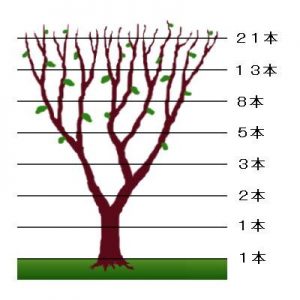
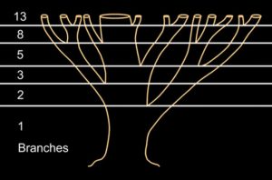
The recursive nature of the L-system rules leads to self-similarity and thereby, fractal-like forms and are easy to describe with an L-system. Plant models and natural-looking organic forms are easy to define, by increasing the recursion level the form slowly ‘grows’ and becomes more complex. Lindenmayer systems are also popular in the generation of artificial life.
The simplest L-system to make is simply a growth pattern with 2 branches at the end of every branch.
However, more complex systems use Turtles. Turtles are the interpretation of simple rules of growth. Something can grow in branches using [ ] (whatever is inside brackets). Growth be symbolised by letters ( F and G) WITH RULE SETS AND AXIOMS.
A Decaying Forest tree system
Using the above concepts and the example from Shiffman of growing tree. The code was developed to create random decaying trees over time.
Turtle
+ TURN RIGHT BY ANGLE
– TURN LEFT BY ANGLE
& PITCH DOWN BY ANGLE
^PITCH UP BY ANGLE
\ ROLL LEFT BY ANGLE
/ ROLL RIGHT BY ANGLE
| TURN AROUND BY 180 DEGREES
F move FORWARD by 1 unit
[] new BRANCH (whatever is inside brackets)
T move TROPISM BY 1 UNIT
Cloners!
group 1 = I
group 2 =J
group 3 =K
group 4 = L
The parameters in the Turtle and Values tabs are meant for advanced users with programming experience (these tabs contain an entire L-System). Those of you with little or no programming experience should, however, not be scared off. In the following are several variable examples.
Make sure you first set Mode to Turtle.
Brief introduction to L-Systems
In the following pages, the L(indenmayer)-Systems are briefly explained. Additional books or online resources are available that offer an in-depth explanation of these systems (the pdf document “The Algorithmic Beauty of Plants” from Przemyslaw Prusinkiewicz and Astrid Lindenmayer is based on use with CINEMA 4D and can be downloaded at http://algorithmicbotany.org/papers#abop).
L-Systems are usually used for similating plant growth and similar effects. Combined with MoGraph, these can be used to create spectacular growth simulations by placing a MoSpline object into a Sweep NURBS object, thus creating a renderable object (Splines can be rendered directly using Sketch and Toon or HAIR).
Simply put, an L-System executes a series of commands that define how and where new branches should grow. It is a self-producing system that can replace existing branches with new ones.
The basic principles are fairly simple and are based on a system called “Turtle System”. A (virtual) turtle is sent on its way via simple commands. This path is represented by a Spline.
The 3 most important commands are:
If you enter the sequence F++F++F in the Premise field it translates to: “Take one step Forward; turn twice to the right; take another step Forward; turn twice to the right; take another step Forward.”
How big each step is and how large the angle of rotation is can be defined in the Values tab via the Default Movement and Default Angle values, respectively. Or, as described below, by placing them in parenthesis. If Default Angle is set to 60° a perfect triangle will result for our example:

 Two different command codes: left F++F++F; right: F-F++F-F (each with a Default Angle of 60°.
This lets you create branch-like shapes. A very interesting function of L-Systems is its integrated replacement system with which individual branches can be replaced by others. This can also be done recursively, which lets you create very complex branching with simple command codes. If this sounds confusing, the following example can shed some more light on what’s involved:
So far you have only entered single-line command codes that were executed only once. Now enter the following command code into the respective fields:
Premise field: F++F++F
Rules field: F = F-F++F-F
As you can see, the Rules code line contains an assignment (in the following refered to as Rule) in which “F” is assigned several symbols that in turn will (internally) be inserted into the Premise line of code.
If written out in its entirety, the command line code would read as follows (replace the F in the Premise line of code with the code following the “F” in the Rules line of code):
F-F++F-F++F-F++F-F++F-F++F-F
This represents the second shape from left in the image below. Since each F in the Premise code is replaced by the Rule, each straight line will be replaced by the more complex line.
 Change of shape when each F is replaced by the “F-F++F-F” code.
And this replacement process can be repeated indefinitely (well, not quite, since your computer will probably throw in the towel after the exponentially increasing complexity of the Splines starts to grow…). How often this replacement process is repeated is defined by the Growth value, which replaces each F with the Rules code. Incidentally, fractals work the same way.
Of course placeholders can be used as well so that not necessarily each F has to be used. After all, this would be unrealistic for growing formations – growth in length does not always occur only at the end of branches, etc.
For this you can use placeholders (letters that do not represent any Turtle command) such as A, B, C, D, (but NOT “F” because it is the default “one unit forward command”).
Type the following into the respective fields:
Premise: FA
Rules: A=+F-FA

Since the Rule ends with an A, an increasing Growth value will result in the formation growing endlessly (Default Angle is set to 90°).
Tip:
This simple-looking replacement rules can create an amazingly complex geometry over several generations (see below). If symbols are used incorrectly you can end up crashing your computer. So be careful when experimenting and save your work often (even in a simple text editor). It is also very helpful if you set Display Mode to Line.
The code we have used so far has consisted of a single, uninterrupted line of code. However, L-Systems first become interesting when real branches are created, i.e. new lines that branch from existing lines. And this can be achieved by using square brackes ([ ]). The command sequence within a square bracket is viewed as a separate branch (and creates a new Turtle). After the branch has been created the turtle will return to the starting point prior to the square brackets and continue with the command sequence following the square brackets.
Type the following into the Premise field:
F[+F][-F[-F]F]F[+F][-F]
 This is the result of the command code above with a Default Angle of 30°.
If you now enter F into the Premise field and the above code (F=F[+F][-F[-F]F]F[+F][-F] ) into the Rules field, each F will be replaced by the braches at the left of the image. Increasing the Growth value will let the branch continue to grow because each straight line will be perpetually replaced by a new branch. If you look closely you will see the branch pattern at the left repeated in the tree at the right (highlighted in green).
This is an easy method of creating complex plant-like branching:
 Various command codes. Note that any letter (in this example “A”) can be used as a placeholder. At the bottom right of the image a Default Angle value of 90° was used.
Until now we have generated everything on a flat plane. Since branching doesn’t only take place on a single plane but in every direction, command symbols exist that also makes this possible.
These are (a degree value can be added in brackets after the command symbols):
& or ^: rotate around the Turtle’s transverse axis
\ or / : rotate around the Turtle’s longitudal axis
Type the following into the Premise field: F&F\ (90)^F+F:
 The 90° after the “/” are not really necessary because the Default Angle value will be applied for small specifications.
The result is the Spline pictured above. The turtle moves forward (F), rotates at a right-angle around its transverse axis (&, Default Angle is set to 90°), moves forward again (F), rotates 90° around its longitudal axis (\ (90)), then 90° around its transverse axis (^), moves forward again (F), turns right (+) and finally moves forward again (F).
If you use this method to create branched spatial formations, real bushes and trees can be created.
User Data

You can use the User Data as variables in a sequence of symbols. In the image above an Angle parameter was added to the User Data that was then substituted in parenthesis for ^ (turtle rotates around transverse axis) in the Premise field.
Special characters and spaces should not be included in the variable names. Underscores are recognized (e.g. “second_length”) as is capitalization.
Formulas
Formulas, including defined variables (e.g. F(_growth*2), can be used instead of normal digits. The following are available:

Example “Total/Index”
Let’s say you have the string F(_index)F(_index), which consists of two commands. The string performs the same function as F(1)F(2) (one unit forwards then two units forward). For example, since “_total” is the total number of commands, a spiral can be created with the following command:
Premise: FA
Rule: A=+(20*_index/_total)FA
Example “_level”
Let’s say you have the following command:
Premise: A
Rule: A=FA
The following level values will result (shown here in parentheses for demonstration purposes – these will NOT actually be shown):
Growth = 0 : A(0)
Growth = 1 : F(1)A(1)
Growth = 2 : F(1)F(2)A(2)
Growth = 3 : F(1)F(2)F(3)A(3)
Now that you know how the “_index” numbering is done, take a look at the following command:
Premise: FA
Rule: A=+F(_level*10)A
…creates the following spiral with Default Angle set to 90°:

Example “_arg”
Just as you can define F(a,b,c)=F(a*2,b*2,c*2) to set parameters for Turtle commands (in this example F) you can also use the “_arg” command. These don’t have to be evaluated at the beginning. F=F (_arg1*2,_arg2*2,_arg3*2) does the same as the command above.
Advanced syntax variations
The following syntax is also possible:
Premise: F(2)F(1,2)F(2,3)
Rule : F(a,b) = F(a*2,b*2)
All Fs will be replaced and wherever “a” or “b” appear within the Rule existing F arguments will be handled as follows:
F(2*2,1*2)F(1*2,2*2)F(2*2,3*2) which logically equates to F(4,2)F(2,4)F(4,6).
Rule constructs like the following are also possible:
F(a,b):(a>10)=F(a,b)+F(a/2)
This Rule will, for example. only be applied if the value of the first argument is greater than 10.
In the following example both syntax variations above were combined and produce an interesting effect:
Example “fruits”

In the example above, several branches grow simultaneously. When one branch has finished growing a sphere will be placed at the end of the branch (requires the command J, see example: Klon-Objekt).
Note that “B(6)” is defined in the first Rule and that “B(h-1)” reduces the argument by 1 in Rule 2 until “h=0” finally sets the sphere in Rule 3.
Take a look at the console to see the entire string (but first click on the Result String to Console button).
Further details regarding formulas can be found in the attachment.
Premise
Enter the premise here. This is most often a single-letter command (see Rules) or a placeholder to which content is added in the Rule field. In the following pages you will find numerous examples of how strings can look.
Context Ignore
Here you can define a series of symbols (commands) that will be ignored by context rules. Example:
You have the following constellation:
Premise: A+B+C+D+E+F
Rules: A
Rules

Example “creating polygons”

Take a look at the second line of the Rule field:
L=[{.-f.+f.+f.++++f.+f.+f.+f}]
Between the curly bracktes (these define a polygon), a specific number of polygon points is defined (each begins with a “.”) between which a polygon is created. Because the curly brackets are contained within square brackets, the turtle will be reset to its point prior to creating the leaf after each leaf has been created.
The entire leaf will be assigned to an “L” and the Rule in the line above will create a complete leaf wherever an “L” exists.
Note that the MoSpline can produce either a Spline OR a polygon. If you want to produce both simultaneously, use the Destination Spline.
Example “multiply/divide”

If you use a self-replacing sequence of symbols in the Rules field (e.g. A=F+BA), a multiplier or divisor (“, !, ;, _, ?, @) can be used to increase or decrease the value of each new Generator.
Example “cutting a branch”

If you take a look at this Rule you will see that the placeholders A, B, C and D have been added to the premise. For various Growth values, the Rules now define the replacement of each placeholder with a % value, which means that the following symbols will be cut off at that point on (and per) each branch.
Example “Cloner object”
 If the Growth value is animated, this structure can grow exuberantly (incl. growing clone).
Note how J and K are used in the Rule (these could be replaced with (1,1,1,1) and (1,1,1,1), repectively, and if the parentheses argument were omitted each would use the standard value) that refers to the clones of a Cloner object. The mode must be set accordingly for both Cloner objects:
I(1,1,1,1) reflects Group 1
J(1,1,1,1) reflects Group 2
K(1,1,1,1) reflects Group 3
L(1,1,1,1) reflects Group 4
Note that one Rule
Premise: FA
Rules: A=FX
X=J(1,1,1,1)
may function but the clones don’t grow steplessly but are simply displayed abruptly.
Example “index”

A Cloner object’s Child objects are numbered sequentially (starting with “0”). If, for example, you define A=FJ(2,1,1,1)A (the RGB values can be omitted), the Cloner object will only use the object with the index “2” (left of the sphere). If you use A=J(rnd(2))A on the right side, a clone will be placed randomly in accordance with a number between “0” and “2” that is also chosen randomly.
Example “random growth”
 Different limits generate different shapes.
This Rule in combination with varied User Data values for Limit1 and Limit2 (together, these values should equal 100%) can be used to create differing but very similar “plants” (Stochastic L-Systems. The conditions (rnd(1)<) or (rnd(1)>) determine randomly which of the 3 Rules will be applied (each with a new random selection for each new Generator, i.e. larger Growth parameter).
Example “context rules”
Rules can also be written in the following form:
Premise: ABC
Rule: A<B=C
Result (if Growth > 1): ACC
So what will happen? This depends on the sequence within the result string. The Rule “A<B=C” searches for instances within the string where a “B” directly follows an “A” and replaces the “B” by a “C”.
If, on the other hand, you enter “A>B=C”, the “A” to the left of a “B” will replaced by “C” (the result would be “CBC”).
For the Rule “AB=C” it cannot be determined which symbol should be replaced by “C”. In this case both will be replaced by “C” (the result would be “CCC”).
Result
Displays syntax errors.
Result String to Console
Clicking on this button will display the symbol sequence currently in effect, taking into account all Rules and the Growth parameter, in the Console. Such a sequence can, for example, look like this (this is the sequence of symbold from the fruits example with Growth set to 4):

Abstraction
Building on the L-system process of growth with abstraction.

Differentiated mathematics and morphogenetic processes
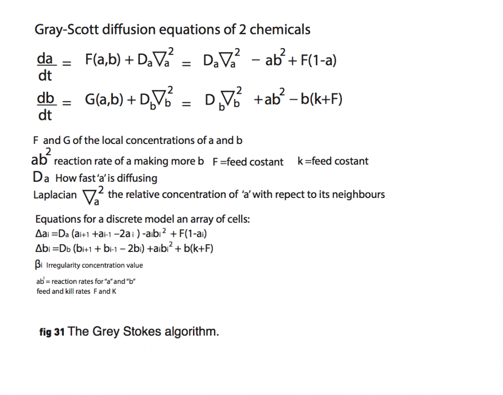
Alan Turing published a paper in 1952, The chemical basis of morphogenesis’ (ref 5). on the spontaneous formation of patterns in systems undergoing reaction and diffusion of their ingredients. Turing devised a mathematical model that explained how random fluctuations can drive the emergence of pattern and structure from initial uniformity.
Turing speculated that among the molecular ingredients of this bundle of cells are components called morphogens (‘shape-formers’), which are somehow responsible for triggering the development of a cell or tissue along a certain pathway. More specifically, a morphogen is a signalling molecule that acts directly on cells to produce specific cellular responses depending on its local concentration.
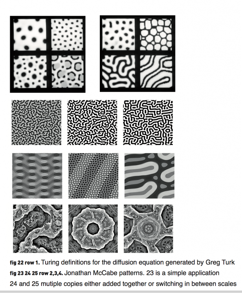
Turing diffusion equations of 2 chemicals:
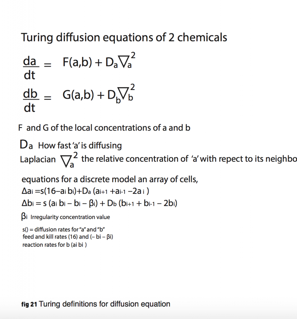
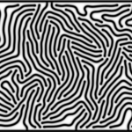
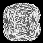
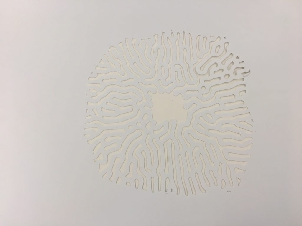
My artefact consisted of a implemented interactive diffusion equation algorithm based on the Gray-Scott model (ref. 22). Figure 30. The user is able to dynamically control thealgorithm by clicking to add more “cells” and by dragging the mouse to change the feed parameter (F) and the kill parameter (k).

The Artefact
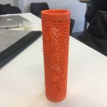
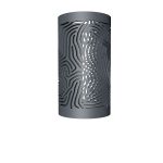
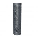
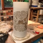
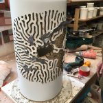
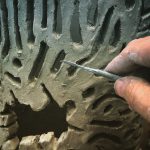
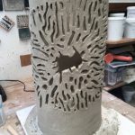
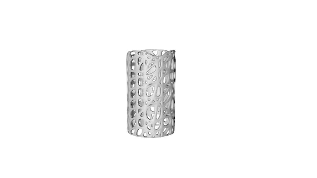
The software algorithm was run with a Gray-Scott algorithm. The results are shown below. The results show 2d outputs transferred into 3d models and output as prototypes. The idea here is to produce 4 large cylindrical ceramic lights ( approx 90cm height x 30cm diameter).


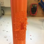


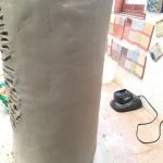
Clay Models


The importance Voronoi Patterns in Nature.
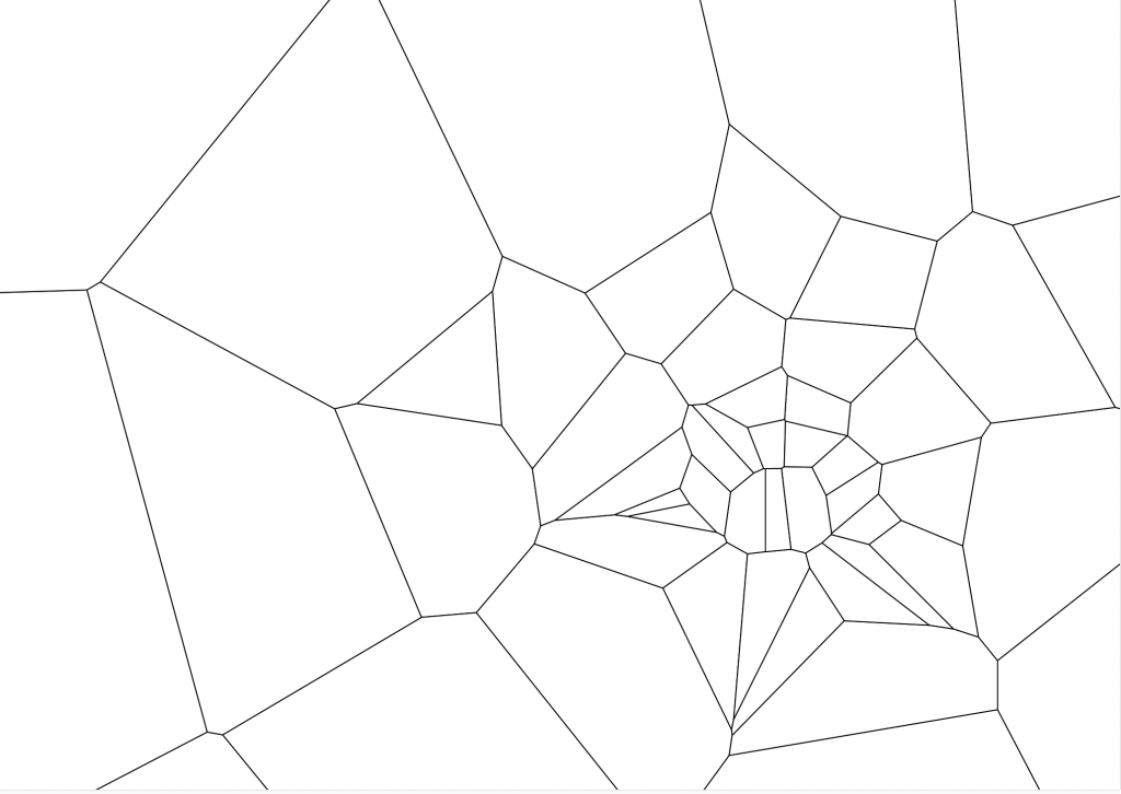
Frei Otto was the father of ‘form nding’ in architecture: using natural morphogenesis techniques to inspire his own architecture creations. He was one the first people to realize the power of morphogenetic design. The first experiment looks at a natural distance experiment using a defined limited surface area with a set of natural floating points that all use repulsive magnets to set there distance. See Figure below:

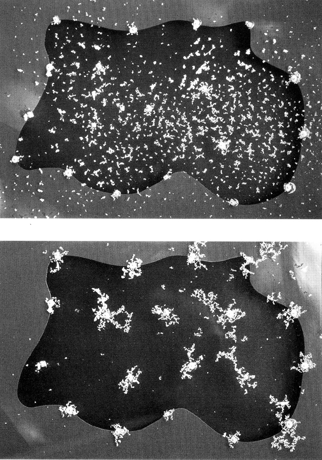

He found that that the arrangement of equal distancing method he saw within natural forces ( using the experiment of needles and magnets floating on water) was the method nature used to balance out the formation of cell patterns and skin patterns on animal and natural organisms. This same formula has taken to the name of Voronoi patterns. Named after Georgy Voronoi. In this case each site pk is simply a point, and its corresponding Voronoi cell Rk consists of every point in the Euclidean plane whose distance to pk is less than or equal to its distance to any other pk. If we see the diagram below:

Looking at the diagram above the 4 squares (black) indicate 4 areas of “cell” growth. If we assume for moment each cell can exhibit the same force of growth on each other, then we can correctly assume the midpoint euclidean distance between each growth area presents a balance of opposing forces of growth. If we draw a “normal” line at the mid-point of this line (which are part of the Delaunay Triangulation.) We then see the black polygonal lines surrounding each rectangle growth centre. The pixel (x,y) can be part of one of the polygonal shapes by answering the question: what is the smallest distance to each of the cell objects? The answer will tell you which polygonal shape the pixel belongs too.
How useful is this?
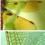
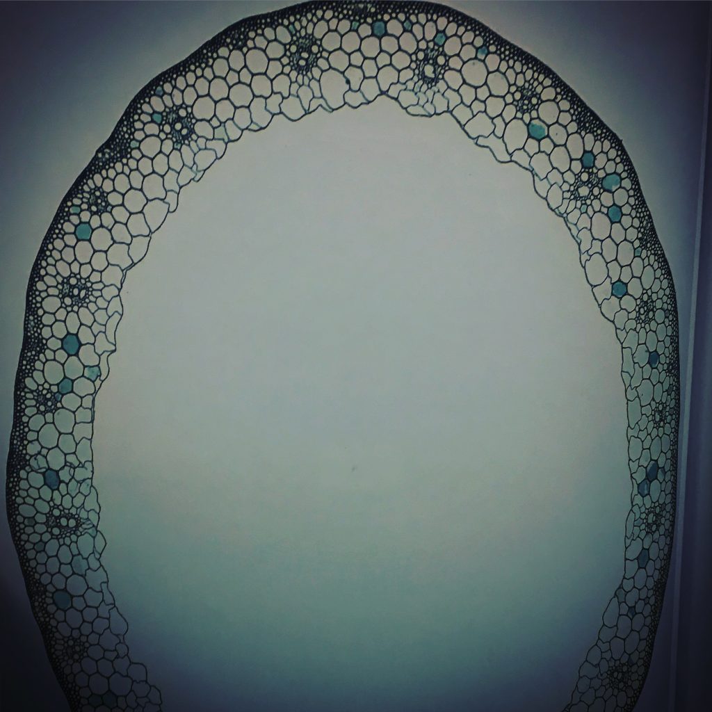
Take a look at all the natural uses of Voronoi type formation:


The Artefact
The results are shown below. The results show 2d outputs transferred into 3d models and output as prototypes. The idea here is to produce 4 large cylindrical ceramic lights ( approx 90cm height x 30cm diameter).


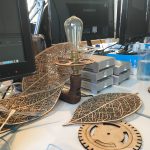
Other physical Voronoi processes


The basis of the research for the MA is built upon the foundations of my previous research paper on Morphogenesis:
MORPHOGEN_PROJ_COLINHIGGS_08H_240318
The research will include practical and theory led code and initially below is my research into using physical materials.
My idea is to create a installation that is Morphogenetic in nature with either the use of physical materials or not and incorporates Morphogenetic theory and code
PHYSICAL MATERIALS
using the book Simply Material I gathered together some interesting materials
Click on the group of images below to enlarge; 1-13 images


Important features:
Sculpting forms to create something morphogenetic.
Pros: Can be quite beautiful in appearance
Cons: Non interactive and difficult to make interactive
Notes
1. Acrylics can be bent but static could use lights
2. Wood + cogs and pulleys and motors can work but messy
3. Glass is beautiful but static unless lights used inside
4. Bamboo is beautiful (the spheres are wicked with light inside)
5. Semi transparent glass is beautiful but difficult to work with
6. The crushed silk is gorgeous and looks amazing and organic:
Problem: a new skill
7. Japanese salt: Getting the salt to create certain structures looks wicked
Problem: how so make the structures?
8. Floating lights could be promising: investigate further
Studio Address:
Oostzijde 355
1508 EP Zaandam,
The Netherlands
+31 (0)6 16.23.23.99
info@ericklarenbeek.com
www.ericklarenbeek.com
http://www.cameronballoons.co.uk/fabricengineering
For all your great ideas, contact us.+44 (0)117 9637216
sales@cameronballoons.co.uk
9. Clay 3d printers
Goldsmiths have a series of clay printers could be feasible to interact with in certain time periods: investigate further. (A fuse deposition modeller a 3D print). Maybe possible to obtain point cloud? (export to 3d app and then make a model and re-export and print.)
https://youtu.be/eyNrl0vOk5I
https://brekel.com/brekel-pro-pointcloud-v2/
10. Small neon lights: no
11. polystyrene elements like a honeycomb : Problem: difficult to make
12. fibre optics : Problem: difficult to make?
The Beginners Guide to Fiber Optics – Instructables
13. Fabric bending structures Problem: difficult to make?
Using Transmaterial 2
I found the following materials: IMAGES 1-12

Click on the group of images below to enlarge; 1-12 images


1.-2. Steel cutting Templates. Kinda like laser cutting for steel Problem: difficult to make? Ask Adam
3. Ratan woven lights kinetic sculptures? Problem: difficult to make interactive
https://youtu.be/QV_C7_NjTjc
4. Memory materials: steam bending wood and plastics
Problem: difficult to make interactive
5. Arrays of LEDS Problem: difficult flexibility
6. Stretch Material Tensegrity cloth architecture. Problem: Not that easy to make


7. Colour changing fabric.
8. fibre optic weaves
9. Dune . Interactive light LED’s
Great work….Massive LED Matrix. Problem: massive array of LEDS. Investigate arrays
10. Large LED array
using the book Transmaterial Next
I found the following materials: IMAGES 1-12


CSM Physical Materials
Photos taken inside CSM materials Library.
cocofoam: very light weight shell
Foldtex: www.foldtex.com wooden pieces on cloth
Keraflex: paper thin porcelain. www.keralfex.us.
Fossshape: www.wonderflexworld.com
Ultrathin edible discs. www.molecularrecipies.com
Formetal.
Photochromatic pigment
Technogel.
indoor terrains grass. www.brightgreen.co.uk
Foamceramics. www.marjanvanaubel.com
Honeycomb metal .www.plascore.com
A Touch of Code from the Book of Installations


Best Installation ideas:
using TOUCH crystals and salt. SALT IS DIGITAL
Replicating a printing process (using a printer of some form)
Release of a smoke
floor panels….
Using Gestures
Floating robots
Projections on floors always nice ( imaginary vegetation)
Optical fibres
interactive lanscapeof lights
displays on walls reacting to people….
physical glowing balls
colored glass blocks
taking 3d prints from censored images (kinect 3d)
Dichroitic film
Pendulim drawing with electromagnets
Some form of live drawing process
Physical arrays of objects that can change state.
Create physical grid arrays.
Physical sound sculpture.
 –
–